Features
The builder has the following features available when creating keyboard layouts.
Plate Layout
The keyboard layout is specified by using the Raw data from the keyboard-layout-editor.com (KLE) tool. The data from KLE defines the layout of the keyboard, or the footprint of the keys.

Once you have a layout specified, you can modify individual keys by adding or editing the key’s details object. This details object is a set of parameters defined inside curly brackets before the key. For example, Tab is defined as {w:1.5},"Tab".
The following parameters can be specified to override the default settings on individual keys.
Rotate Switch Cutout
{_r:<degrees>}: Example,{_r:90},"". Rotate the switch cutout independent of the stabilizer cutout (assuming there is one).
Set in Switch Type vs Adding_r:90

Rotate Stabilizer Cutout
{_rs:<degrees>}: Example,{_rs:180},"". Rotate the stabilizer cutout independent of the switch cutout.
Set in Stabilizer Type vs Adding_rs:180

Switch Cutout Type
{_t:<1-4>}: Example,{_t:1},"". Numbers are in the same order as the images.
Set in Switch Type vs Adding_t:1

Stabilizer Cutout Type
{_s:<0-4>}: Example,{_s:3},"". Numbers are in the same order as the dropdown list. The special{_s:0},""options is used to remove the stabilizer completely for an otherwise stabilized key.
Set in Stabilizer Type vs Adding_s:3

Custom Polygons
{_c:"<index>[,index]"}: Example,{_c:"0,1"}. The index values are found in the Custom Polygons section associated with each line item. The specified custom polygon(s) will be drawn relative to the center point of the specific switch.
Set in Stabilizer Type vs Adding_c:"0,1"with the appropriate Custom Polygons

Cutting Kerf
{_k:<mm>}: Example,{_k:0.25},"". The kerf value for an individual switch/stabilizer cutout, this overrides the value set in the Kerf section. Values are in mm (without the unit).
Set in Kerf vs Adding_k:1

Here is an example using all of them together: {_r:90, _rs:180, _t:1, _s:2, _k:0.25},""
Switch Type
There are currently 4 different switch cutouts which you can choose from. Each have their own pros and cons which we will cover in this section.
Classic MX Cutout
{_t:1}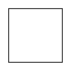 The standard cutout used by all non-custom keyboards. This cutout does not allow you to open the switches without desoldering them from the PCB. If you are hand wiring a keyboard, this cutout is the most stable and you will be able to unclip the switch from the plate without desoldering.
MX + Alps Cutout
{_t:2}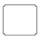 A cutout with a good balance of flexibility and fabrication cost. It is less expensive to produce than any of the other openable cutouts. It supports MX switches with the ability to open them without desoldering as well as Alps switches. It is known to be the least stable of all the cutouts, so it does have trade-offs.
MX Openable Cutout
{_t:3}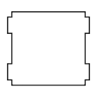 The most popular MX specific cutout which allows for switch opening without desoldering from the PCB. It is the most stable openable MX cutout, but you will pay a little more to get a plate cut with this cutout than the previous cutout.
Alps Cutout
{_t:4}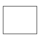 A standard Alps cutout with no frills. It is compatible with the old school Alps as well as the Matias Alps switches.
Stabilizer Type
There are currently 4 different stabilizer cutouts which you can choose from.
Cherry + Costar Stabilizer
{_s:1}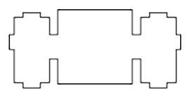 A stabilizer cutout which supports; Cherry PCB Mount, Cherry Plate Mount and Costar stabilizers. While this cutout supports Cherry Plate Mount stabilizers, if you know you are going to use that stabilizer, the Cherry Stabilizer cutout is a better option. This is due to the fact the extra top cutout is where the stabilizer clips onto the plate, so it won’t clip in there.
Cherry Stabilizer
{_s:2}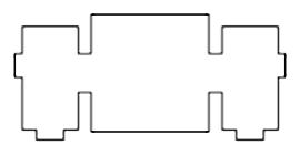 A stabilizer cutout which supports both Cherry PCB Mount and Cherry Plate Mount stabilizers. If you plan to use Cherry Plate Mount stabilizers, this is your best option because the stabilizer will clip in on the top.
Costar Stabilizer
{_s:3}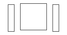 A stabilizer cutout which only supports Costar stabilizers. This is the cheapest MX compatible stabilizer cutout, so it will have a lower fabrication cost.
Alps Stabilizer
{_s:4}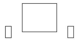 A stabilizer cutout which supports Alps stabilizers for known sizes. If the size is not a known Alps stabilizer size, a Costar will be drawn instead. EG: A 2.25 unit key.
Case Type
The Case Type lets you choose how your layout is installed. You have a few different options, outlined as follows:
None - Don’t define a case at all. This type will produce only the switch layer with your layout on it. You still have options for modifying this output with things like Edge Padding or Custom Polygons, but it will not produce additional layers for building a case. If you would like additional layers for actually building a full case, choose the Sandwich case type.
Poker (60%) - Draw a plate to be used with standard Poker compatible 60% cases. This layout is based on the GH60 PCB drawings. The holes default to 5mm in diameter, so the screw is intended to pass through the plate with the plate/PCB being held to the case by fixing the PCB to the case. If you would like to use a Poker style case and hand wire the board instead of using a PCB, you can use standoffs and set the Hole Diameter smaller to make the screws support the plate.
Sandwich - Draw a plate as well as additional layers to build a layered case. The
switchlayer goes on the top, then there are essentially ring layers to create empty space for the PCB or wiring and abottomplate. There are two types of ring layers;openwhich has a cutout for the USB connector, andclosedwhich has no cutouts. You can choose how many of each layer is suitable for your case. This case type produces the CAD files for all the layers required to build a layered sandwich case.
Hole Diameter
Note
This option only applies to the Poker case type.
The default hole (and slot) diameter is 5mm for the Poker case type. This option lets you specify what diameter you want these holes and slots to be. This is useful if you do not have a PCB to hold the plate to the case. This would allow you to use a value like 2.5mm and use M2 screws with a standoff (a nut or nylon washers) to fix the plate to the Poker case itself. Usually the screws pass through the Poker plate and the PCB is used to hold the plate to the case. This allows you to change this default behavior and make fix the plate directly to the Poker case.
USB Cutout
Note
This option only applies to the Sandwich case type.
These option lets you move the USB cutout location in the open layer of the Sandwich case type. The default of 0mm places the USB cutout at the center of the total width of the layout on the top side of the open layer of the case. The width of the cutout defaults to 10mm, and can be set to your desired width. It is very difficult to represent the location of the cutout in relation to a potential PCB in a usable fashion, so instead I work entirely off the width and center points of the total case drawn. If you enter values that would put the USB cutout outside of the inner opening of the case, the cutout will be placed with one edge against the side of the inner opening. This will put the edge of the cutout the edge width distance from the outside edge of the case.
location controls: 0 = center, neg (-) = move left, pos (+) = move right
Example: GH60 = -124.3
Mount Holes
Note
This option only applies to the Sandwich case type.
The Sandwich case type has the option to add mount holes which will be used to screw together the case. This feature is optional because some people may choose to glue, or otherwise fix the layers together, so mount holes would not be desired.
If specified, the number of holes must be greater than or equal to 4 and must be an even number. The first 4 holes will always be placed at the corners of the case, and the remaining holes will then be evenly distributed based on the largest remaining space. The holes will be evenly distributed around the board according to a combination of the diameter of the hole and the Edge Padding. If the Edge Padding is greater than the hole diameter, then the holes will be evenly distributed around all 4 sides of the case. If the Edge Padding is less than or equal to the hole diameter on two opposing sides, then the holes will be evenly distributed on the other two opposing sides of the case.
The edge width defines the width of the wall on all four sides of the sandwich case, assuming the Edge Padding is greater than or equal to the edge width. The holes will be placed along the center of the edge width. Be sure to leave enough material on both sides of the holes to maintain structural integrity when the case is assembled. The difference between the Edge Padding and the edge width will represent empty space inside the case. This is useful if you plan to put additional components inside the keyboard case, like a Raspberry Pi for example.
You will want to choose the diameter of the hole based on the screws you plan to use for assembly. For example, if you plan to use an M3 screw with a nut on the opposite side, then you would likely want a value of about 3.2mm. If you plan to use an M3 screw and tap the hole so no nut is required, then you would likely want a value of about 2.5mm.
Edge Padding
The edge padding defines the amount of space between the edge of the case and the edge of the keyboard layout, which essentially lines up with the edge of the key cap. This feature is optional for all case types except the Sandwich case.
The edge padding can be either positive or negative. A positive value will add to the total case size in that direction. A negative value will cut away from the plate layer that much material. Be careful to leave enough material next to the switches if you use negative values. A value of 0 will remove that wall of the sandwich case, assuming Kerf is not set to a positive value. If Kerf is set to a positive value, then you will need to define the padding as negative kerf (eg: -0.15) in order to remove that wall of the case completely. Please note that ordering from builder.swillkb.com will result in your layout being redrawn with the optimal kerf for the selected vendor. If you are trying to remove case walls, you may have to edit your Edge Padding to account for the applied kerf.
The edge padding is required on at least two opposing sides of the Sandwich case. If you leave two opposing sides open on a Sandwich case, you reduce the material waste to fabricate the middle layers, so the fabrication costs are considerably less.
Plate Corners
The plate corners feature lets you add rounded corners to your plate/case, which adds a really nice aesthetic to a case.
The value entered defines the radius of each corner in millimeters.
Custom Polygons
The custom polygons feature lets you totally customize the output of your plate/case. If you want additional cutouts, such as holes or adapting a cutout, it can be done with a Cut operation. If you want to add additional material to the case, to make it more interesting or to serve a specific purpose, use the Add operation. The polygon operations can be done on any combination of drawn layers.
There are two different polygon operations which you can use.
- Add - This will add material according to the defined path for all selected layers.
- Cut - This will remove material according to the defined path for all selected layers.
Currently there are four types of polygons which can be added or removed from the drawings.
Circle
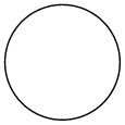 Defines a circle with a
diameterwhich is placed at each of thecircle centerslocations, according to therelative topoints. If more than onerelative topoint is specified the set of shapes is duplicated at eachrelative tolocation.Superellipse
 Defines a superellipse with a concave
radiuswhich is placed at each of thesuperellipse centerslocations, according to therelative topoints. If more than onerelative topoint is specified the set of shapes is duplicated at eachrelative tolocation. A superellipse is primarily used to set custom rounded corners on both concave or convex rectangular corners.Rectangle
 Defines a rectangle with a
widthandheightwhich is placed at each of therectangle centerslocations, according to therelative topoints. If more than onerelative topoint is specified the set of shapes is duplicated at eachrelative tolocation.Rounded Rectangle
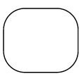 Defines a rectangle with rounded corners according the
radiuswhich will have awidthandheightand will be placed at each of therounded rectangle centerslocations, according to therelative topoints. If more than onerelative topoint is specified the set of shapes is duplicated at eachrelative tolocation.Custom Polygon
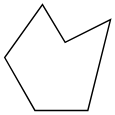 You define a custom polygon by defining a
closed path of pointsin clockwise order, and this polygon will be places at each of the definedrelative topoints.
If it is not clear from above, a single polygon definition can be placed in multiple locations by defining more than one center and/or relative to point.
Note
If you define a shape and do not specify any relative to points, the shape will not be drawn. However, if you use the {_c:"<index>[,index]"},"key" formatting defined in the Plate Layout section, the center of the associated key will be used as the relative to point. This is very useful for placing custom cutouts relative to specific keys in the plate layout.
Coordinates and Positioning
Points are defined inside square brackets ([ ]) and separated by a semicolon (;).
The point [0,0] is defined to be the center of the case. The values x and y can be used in the coordinate system to represent 1⁄2 the total width and 1⁄2 the total height respectively. This means the following locations are represented as follows; top left = [-x,-y], top right = [x,-y], bottom left = [-x,y], bottom right = [x,y].
In addition to being able to use x and y to help represent a point in space, you can also represent a coordinate as a set of arithmetic equations. For example, if you wanted to represent a point on the top side of the case which splits the difference between the center of the board and 20mm from the top left corner, you would represent that point as: [(-x+20)/2, -y]. This provides a lot of flexibility in representing points related to the plate/case and enables you to have handle symmetry in an intuitive manor.
In addition to being able to place custom polygons based on positioning relative the size of the case, custom polygons can be placed based on the center point of a switch for a specific key in the layout. This is done by adding the {_c:"0,1"} details object, where 0 and 1 are the index values for the custom polygons to be drawn relative to that switch center. This is very useful if you want to modify things like the stabilizer cutout for a 3mm switch plate so a cherry stabilizer wire has somewhere to go.
Check the Plate Layout section for additional details regarding the individual key based placement.
Example 1
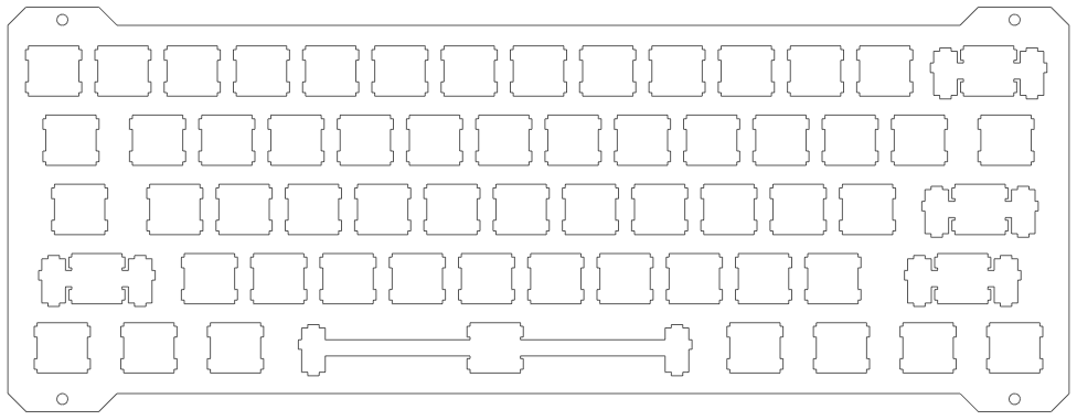
This feature is best described with an example, so here is a 60% layout with added tabs and holes in the tabs.
Custom Polygon
Op: Add
Rel-To: [-x,-y]; [x-30,-y]; [x-30,y]; [-x,y]
Path: [0,0]; [5,-5]; [25,-5]; [30,0]; [25,5]; [5,5]
Circle
Op: Cut
Diameter: 3
Rel-To: [0,0]
Centers: [-x+15,-y-1.5]; [x-15,-y-1.5]; [-x+15,y+1.5]; [x-15,y+1.5]
Example 2
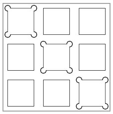
In this contrived example, the use of cutouts associated with specific keys is illustrated.
Plate Layout
[{_c:"0"},"","",""],
["",{_c:"0"},"",""],
["","",{_c:"0"},""]
Circle (index: 0)
Op: Cut
Diameter: 3
Rel-To: not defined
Centers: [7,7];[-7,7];[-7,-7];[7,-7]
Kerf
The kerf feature allows you to account for the kerf of the cutting tool when the part is being fabricated. Kerf is the width of the material removed by a cutting tool. If you do not account for kerf, the part will be smaller than expected by 1⁄2 the tool’s kerf value on all cut sides. The kerf is calculated along the cut line, so 1⁄2 will be inside the line and 1⁄2 will be outside the line. So for example, if the kerf of a cutting tool is 0.2mm, that means that an extra 0.1mm will be removed from the plate when it is cut (the other 0.1mm is removed from the off cut). I account for this, so if the kerf is set to 0.2mm, the resulting 14mm square hole would be drawn as a 13.8mm square. Keep in mind that the different processes will have different values for kerf, so check with the manufacturer. Also, keep in mind that the type of material and its thickness plays a role in the width of the kerf.
If you order your job through the builder.swillkb.com tool, then the parts will be redrawn in the tool with the kerf value optimized for the selected fabrication vendor.
Key Unit
The key unit feature allows the default key unit size of 19.05mm to be modified. This feature is useful if a PCB designer has used a value such as 19.00mm instead of the standard 19.05mm for the sizing of a single key unit.
Note: This feature does not modify the spacing of the space bar stabilizer position.
Line Color
The line color feature allows you to adjust the color of the cut lines. Some laser cutters are picky about the color of the cut lines in the SVG, so this lets you conform to their requests. If you need to change the line color for your fabrication shop, specify the new color here. Many colors can be referenced just by specifying the name (eg: blue) but you can also use Hex values (eg: #2E69B3).
Line Weight
The line weight feature allows you to adjust the stroke weight of the cut lines. Some laser cutters are picky about the weight of the cut lines in the SVG, so this lets you conform to their requests. If you need to change the line weight for your fabrication shop, specify the new weight here. The builder defaults to 0.05mm and overrides are expected to be in mm (but only as a floating point number without any mm text).